
 |
 |
EM Green's tensor library for horizontally layered anisotropic medium
By Arvidas Cheryauka and Michael Zhdanov
This library is designed to assist in the development of electromagnetic modeling and inversion programs. This software is developed in MATLAB programming language. Using this library, the software developer is freed from coding the excessively complex algorithms for Green's tensors in a horizontally layered bi-anisotropic medium.
Anisotropic horizontally layered Earth
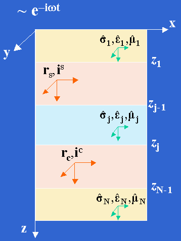
We consider one-dimensional model with a horizontally stratified distribution of electrical conductivity, dielectric permittivity and magnetic permeability tensors. We describe the arbitrary piecewise-uniform distribution of material property functions along the z direction and assume that in the chosen coordinate system these tensor functions in principal axes are transverse isotropic (Figure 1).

The EM Green's tensors represent elementary electrical and magnetic fields excited by the point electrical and magnetic dipoles.
This software has new modeling features:
- Evaluation of all four EM Green's tensors
- High material property contrasts
- Electrical anisotropy
- Magnetic anisotropy
- Arbitrary 1-D model and point-to-point configuration geometries.
It has improved implementation features:
- Matlab language of computing
- Enhanced accuracy
- Fast vectorized evaluation
- Flexible usage for applications.
Here we demonstrate several application examples using the developed software.
Example 1: Cross-well electrical resistivity
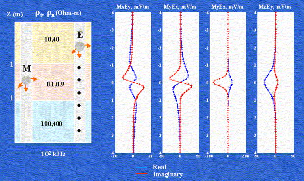
Figure 2 shows the calculation of four nonzero components of 'magnetic-to-electrical' Green's tensor for cross-well resistivity measurements. The model consists of three horisontal layers with constant electrical conductivity tensor functions in each layer. The location of tri-axial magnetic induction source is fixed (z=0 m). Data (three components of electrical field) are observed along a vertical profile. The operating frequency is 100 kHz.

Blue and red colors correspond to the real and imaginary parts of electrical field.
Example 2: Tensor Induction Logging
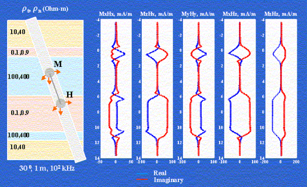
Figure 3 shows the calculation of five nonzero components of 'magnetic-to-magnetic' Green's tensor for tensor induction logging observations. The model includes six high-contrast anisotropic layers. Induction tool with 1 m spacing moves along 30 degree tilted borehole line. Data (components of magnetic field) are collected by the triaxil magnetic receiver. The magnetic source is triaxial induction transmitter. The operating frequency is 100 kHz.

Blue and red colors correspond to the real and imaginary parts of the magnetic field. The field in air is substracted from the quadrature part of the total signal.
References
Cheryauka, A.,B., and M.S. Zhdanov, 2001, Electromagnetic tensor Green's functions in a transverse isotropic layered medium, IEEE Transactions on Geosciences & Remote Sensing (Submitted).