

|
|
|
Foundations of tensor induction well logging
By M.S. Zhdanov, W.D. Kennedy, and E. Peksen
One of the most challenging problems in the field of electromagnetic well logging is the development of interpretation methods for the characterization of conductivity anisotropy in an earth formation. We analyze a new tool design for tensor induction well logging and develop a corresponding theory. The tool has three mutually perpendicular magnetic induction receiver coils and three magnetic induction transmitter coils, that is why it is called "Tensor Induction Tool". In a general case, the anisotropic medium is characterized by the conductivity tensor. In the case of the transverse anisotropic formation this tensor is formed by two conductivity values. They are horizontal conductivity and vertical conductivity. Thus, in order to characterize transverse anisotropic formations, we need to calculate these two conductivity values.
By using the new tool and corresponding theory, one can get information about both conductivities. In this way we can characterize the anisotropic properties of geological formations. This is extremely important information for oil and gas exploration and production.
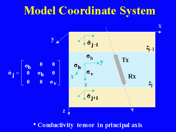
Our goal is to obtain estimates of the components of the conductivity tensor using voltages induced in each of three mutually orthogonal receiver coils of an induction logging instrument. These voltages are obtained from estimates of the magnetic flux linking each coil. The magnetic fields are easily computable from formulas only for sources located at the origin and directed along the coordinate axes of a coordinate frame, called the model coordinate system, chosen to coincide with the principal axes of the conductivity tensor (Figure 1). These formulas give the components of magnetic field in the same coordinate frame.
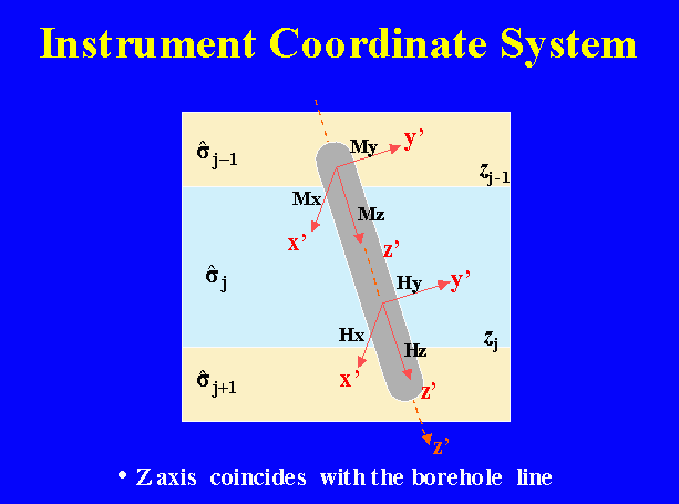
In practice a borehole will penetrate the medium at an angle oblique with respect to this coordinate frame. A logging instrument in such a borehole would be coaxial with the borehole and rotated around the borehole axis by some unknown amount. Thus, a coordinate frame attached to the instrument, called the instrument frame, with three mutually orthogonal axes aligned with the transmitter coil axes will not in general be aligned with the medium frame (Figure 2).
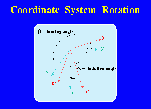
In order to obtain the formulas of the field tensor for an instrument located in an arbitrary orientation with respect to the tensor principal axes, it is necessary to rotate the system of coordinate, as shown in Figure 3.
We examined the basic principles of the tensor induction well logging by numerical simulation of tensor induction well logging data in anisotropic inhomogeneous formations. We analyzed the behavior of the synthetic tensor induction logs through the two-layer and three-layer formations and studied the thin bed resolution. We present first the calculations for a simple two-layer anisotropic model (Figure 4).
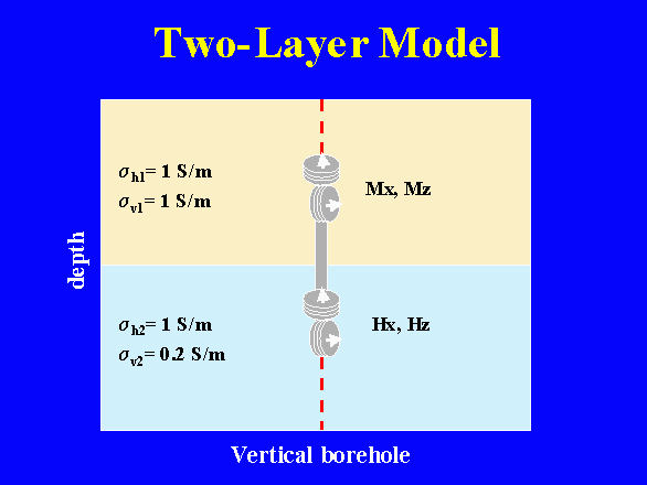
The horizontal conductivity in this model is the same for the top and the bottom layer, while the vertical conductivities of the top and the bottom layers were different. We assumed that the tensor induction logging was conducted by the vertically oriented tool in the imaginary vertical borehole. We calculated the model responses (induction tensor components) for the different parameters of the layers. The synthetic observed data were contaminated by 3% random noise. Using these responses as the theoretical observed data we computed the low frequency apparent conductivities. The more accurate estimation for the apparent conductivities was computed using the Newton inversion. The results are shown in Figure 5. Note that, in this model with the conventional induction tool, we can obtain only horizontal apparent conductivity. The remarkable result is that even in this simple case, the boundary can not be seen by using a conventional apparent conductivity expression. On the contrary, the apparent vertical conductivity clearly demonstrates the position of the boundary.
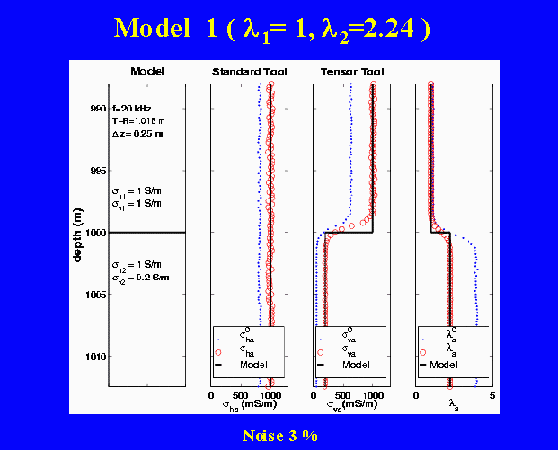
The first panel on the left shows the parameters of the two-layer model. The second two panels present the apparent conductivity curves versus depth. The last panel displays the apparent anisotropy coefficient values computed based on the low frequency asymptotic conductivities, and on the inverted conductivities. The solid black lines show the true parameters of the model. The apparent conductivities and anisotropy coefficient, obtained by the low frequency asymptotic, are shown by the dotted blue lines. The red circles represent the inverted apparent conductivities and anisotropy coefficient.
Figure 6 shows the three-layer anisotropic model. There is no horizontal conductivity variation in this model, while the vertical conductivity of the second layer is different from the top and bottom layers.
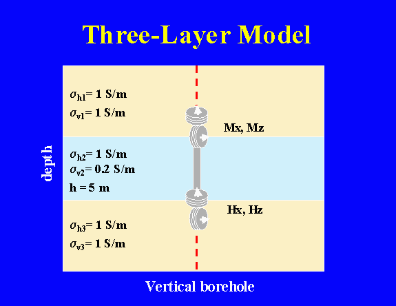
Figure 7 shows the standard and tensor induction logging results for this model. It is an example of the practical situation when the conventional induction logging can miss a geological structure.
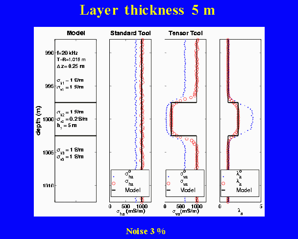
The first panel on the left shows the parameters of the three-layer model. The second two panels present the apparent conductivity curves versus depth. The last panel displays the apparent anisotropy coefficient values computed based on the low frequency asymptotic conductivities, and on the inverted conductivities. The solid black lines show the true parameters of the model. The apparent conductivities and anisotropy coefficient, obtained by the low frequency asymptotic, are shown by the dotted blue lines. The red circles represent the inverted apparent conductivities and anisotropy.
Our results strongly suggest that instruments developed using the triaxial induction principle are sure to add great value to formation evaluation. The further development of principles for tensor induction interpretation in realistic cases is a topic of great interest with much work remaining to be done. We plan to continue this research project in CEMI.
References
Zhdanov, M.S., Cheryauka, A.B., Peksen, E. and W.D. Kennedy, 2000, Modeling and interpretation of tensor induction well logging: Consortium for Electromagnetic Modeling and Inversion, Proceedings of the 2000 Annual Meeting, 103-145.
Zhdanov, M. S., Kennedy, W. D., and E. Peksen, 2001, Foundations of tensor induction well logging: Petrophysics, 42, 588-610.
Peksen, E. and M. S. Zhdanov, 1998, 3-D Modeling and inversion of borehole induction log data in media with complex geometry and conductivity anisotropy: Consortium for Electromagnetic Modeling and Inversion, Proceedings of the 1998 Annual Meeting, 471-500.